Raspberry Pi Serial Port: Ultrasonic Sensor Guide
Do you enjoy or love testing new Raspberry Pi Projects? Maxbotix has put together a tutorial that teaches you how to interface a Raspberry Pi with an ultrasonic sensor to read TTL serial data. You may also want to check out our tutorials on Using an ultrasonic sensor with a Raspberry Pi and how to use USB sensors for a Raspberry Pi.
Getting Started
The Raspberry Pi needs to install an operating system the first time it is used. This article was created for the Raspberry Pi 3 using the Raspbian Jessie operating system (downloaded on 10/06/16). This article was also successfully tested on the Raspberry Pi 2 with the same operating system. This article will be periodically updated as the operating systems, files, and settings are updated and moved.Check out these 5 Ways New Raspbian Jessie Makes Raspberry Pi Even Easier to Use. We hope you enjoy this tutorial, after you’re done reading don’t forget to come back for more Raspberry Pi Projects exclusively provided by MaxBotix.
Key Takeaways
- UART communication needs to be enabled on the Raspberry Pi.
- The required steps will vary depending on the revisions of your operating system.
- The Raspberry Pi is a convenient and affordable way to read ultrasonic sensor range data. Here are 11 reasons why the Raspberry Pi it’s the perfect small server.

TIP For the safety of the electronics on the Raspberry Pi and MaxBotix ultrasonic sensors, please use an ESD strap when working around components. Static discharge could damage components of the Raspberry Pi as well as the ultrasonic sensors.
Required Equipment |
|
Directly Compatible Ultrasonic Sensors |
Ultrasonic Sensors that Require an Inverter |
| The ultrasonic Sensors listed below provide TTL serial data and directly interface with the Raspberry Pi. | The ultrasonic Sensors listed below require an inverter to operate with the Raspberry Pi. |
|
|
| Important: Connect the center square with the outer portion of the pad with a small amount of solder to enable the TTL output on the MB1003 Ultrasonic Sensors from the HRLV-MaxSonar-EZ line. | |
 Before |
 After |
Enable Serial Data on ttyAMA0
We want to enable the RX pin on ttyAMA0 to receive asynchronous serial data. To allow this we need to change the set the enable UART setting in the configurations files.
Open the file /boot/config.txt by using the following command:
sudo nano /boot/config.txt
Scroll to the end of the file and add the following lines to the file. Scroll to the end of the file and add the following lines to the file.
enable_uart=1
dtoverlay=pi3-disable-bt
dtoverlay=pi3-miniuart-btThis will disable bluetooth on the Raspberry Pi 3 and allow serial communication in its place. While this isn’t fully needed for other versions of the Raspberry Pi, it will not impact their performance.
Save and close the file by simultaneously pressing Ctrl and X to exit the screen and then pressing Y to save it.
Optional: Download a Python Script
This is optional, but you may wish to write or download a Python Script to log and store the data you collect with your ultrasonic sensor.
Here is sample python code provided by one of our users to automate the reading of distance values.
Supplying Power to the Sensor
When using an XL-MaxSonar or WR ultrasonic sensor with a Raspberry Pi, it is highly recommended to use an external power supply. The Raspberry Pi is not intended to supply a high enough current draw to power these ultrasonic sensors.
Ultrasonic sensors from the LV-MaxSonar, LV-ProxSonar, HRLV-MaxSonar, and ParkSonar lines can be directly powered by the Raspberry Pi.
TIP You may want to place a capacitor between the power and ground lines immediately before the ultrasonic sensors's pinout. During the ultrasonic sensors transmit, the sensor draws a higher current for a fraction of a second. The higher current draw may cause the Raspberry Pi's microcontroller to begin to shut down. To prevent any issue with long term use, we recommend that you use a capacitor with at least a one microfarad rating to ease the current draw from the Raspberry Pi.
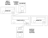
Wiring Instructions

Connect the female end of a jumper to pin 10 of the Raspberry Pi GPIO. This is the RX pin for serial data.
Connect a Mini-Grabber or solder a wire into pin 5 of the sensor, and connect this to the jumper.
Connect your sensor to an appropriate power supply.
Installing Terminal SoftwareThe recommended software for accessing the range data output is Minicom. Please use the following steps to install Minicom. sudo apt‑get install minicomThis will install the Minicom software that is used for reading the serial port. Accessing Ultrasonic Sensor Range Data OutputMinicom is the recommended terminal software for Raspbian Jessie operating system. Please use the steps below to access Minicom and read the range data. minicom -b 9600 -o -D /dev/ttyS0 (For Raspberry Pi 2) Click Here to learn how to use USB ultrasonic sensors for a Raspberry Pi. minicom -b 9600 -o -D /dev/ttyAMA0 This clears the LXTerminal window and you will see a window that looks similar to the image below. |
 |

The number following the ASCII character is the range reading that is output by the ultrasonic sensor. If the readout says R0764, like the image above, the range to the target is 764mm. As the target gets further away from the ultrasonic Sensor , the reported range will increase. If no target is detectable, the target will report maximum range.
Monitoring oil tank level with a MaxBotix ultrasonic sensor
Final Notes & Outcome
Using an ultrasonic Sensor with a Raspberry Pi allows for inexpensive monitoring of tank levels, height measurement, as well as countless other applications that require distance measurement. If you have any applications or code that can be added to this article, or if you would like to share pictures of your setup with us so we can share with others please email webmaster@maxbotix.com.
NOTE: This article was created for the Raspberry Pi 3 using the Raspbian Jessie operating system (downloaded on 7/18/2016).
This article was not written for Raspberry Pi 2.