
Reading MaxSonar Ultrasonic Sensor Beam Patterns
MaxSonar Beam Patterns
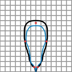
MaxBotix Inc., provides beam patterns for all of our ultrasonic sensors to assist users in choosing the correct sensor for: application, target size, and the distance needed to detect. The beam Patterns provided are approximations to target sizes and distance. Though our beam patterns are accurate for the sensor, there may be slight differences from sensor to sensor for each corresponding part number. All of our sensors are all factory calibrated so additional units of the same part number will have similar beam patterns. All of our sensors have firmware gain changes through the length of the beam. The beam pattern in the data sheet shows the approximate calibrated detection pattern within a few inches on either side (for a similar sized object). The beam width (angle) is not defined because the actual beam width dynamically changes over the course of the range. The beam pattern patterns are provided as approximations to certain size targets. The beam angle at a given distance for a specific target can be calculated by measuring the beam angle from the beam patterns Patterns. If you look at the beam patterns in our data sheets, the beam angle is wide for close objects but then decreases for objects at longer distances; this is done to give our sensors a consistent and narrow detection field. Each beam pattern is a 2D representation of the detection area of the sensor. The beam pattern is actually shaped like a 3D cone (having the same detection pattern both vertically and horizontally). You read our beam patterns by looking at the target size and distance of detection (most are plotted with three or four targets, sizes ranging from the smallest target on the left to the largest target on the right side of the plot). There are typically two voltages plotted which shows the change in the detection pattern at different voltages (3.3V and 5V are typically used voltages). Typically, the higher the voltage supplied to the sensor the larger the beam pattern becomes. As voltage to the sensor is reduced, the size of the beam pattern typically decreases. On the plotted beam patterns, a supplied power of 5V is the black line and 3.3v are red dots. You can see how the beam patterns change with voltage changes. If you view figure 1.1, which is the beam patterns for the HRLV-MaxSonar-EZ1 sensor, you can see the detection zone for a 1/4inch dowel, a 1inch dowel, and a 3.5 inch dowel when operating at 5V, 3.3V or 2.7V. Within the beam patterns the difference between the voltages is also seen. Figure 1.1 HRLV-MaxSonar-EZ1 Beam Pattern
For our LV-MaxSonar, and XL-MaxSonar Line of sensors, the voltages plotted are: 5.0V and 3.3V
The sensor beam patterns can be viewed by clicking the name of each sensor line.
LV-MaxSonar-EZ , XL-MaxSonar-EZ/AE , XL-MaxSonar-WR , HRLV-MaxSonar-EZ ,
HRXL-MaxSonar-WR.
You do not select a beam pattern for the sensor. To select a beam pattern appropriate for your application you select the sensor that matches the beam pattern that is needed. The beam pattern you achieve is determined by your target size. The beam Patterns are provided to help you identify an estimated beam pattern for your application based on your target size versus the plotted beam patterns.
The dowels are essentially vertically hanging targets (pipes). The dowels provide consistence target detection characteristics for a given size target which allows easy comparison of one MaxSonar sensor to another MaxSonar sensor. The smaller the dowel or target, the smaller the detection (beam) pattern is.
People detection is a common use of MaxSonar sensors. People typically are detected anywhere between plot A and plot B. This is because people are soft targets (absorbing most of the sound) and do not have the same reflective properties as hard targets (reflecting almost all of the sound). To read more on using a MaxSonar sensor for people detection click here.
Figure 1.1 HRLV-MaxSonar-EZ1 Beam Pattern
For our LV-MaxSonar, and XL-MaxSonar Line of sensors, the voltages plotted are: 5.0V and 3.3V
The sensor beam patterns can be viewed by clicking the name of each sensor line.
LV-MaxSonar-EZ , XL-MaxSonar-EZ/AE , XL-MaxSonar-WR , HRLV-MaxSonar-EZ ,
HRXL-MaxSonar-WR.
You do not select a beam pattern for the sensor. To select a beam pattern appropriate for your application you select the sensor that matches the beam pattern that is needed. The beam pattern you achieve is determined by your target size. The beam Patterns are provided to help you identify an estimated beam pattern for your application based on your target size versus the plotted beam patterns.
The dowels are essentially vertically hanging targets (pipes). The dowels provide consistence target detection characteristics for a given size target which allows easy comparison of one MaxSonar sensor to another MaxSonar sensor. The smaller the dowel or target, the smaller the detection (beam) pattern is.
People detection is a common use of MaxSonar sensors. People typically are detected anywhere between plot A and plot B. This is because people are soft targets (absorbing most of the sound) and do not have the same reflective properties as hard targets (reflecting almost all of the sound). To read more on using a MaxSonar sensor for people detection click here.
Products Related to the Article
MB1013 HRLV-MaxSonar-EZ1

The HRLV‑MaxSonar‑EZ1 is a great choice for use where sensitivity is needed along with side object rejection....
Buy NowMB1222 I2CXL-MaxSonar-EZ2
The I2CXL-MaxSonar-EZ sensors now feature an I2C bus. This allows for easy I2C integration...
Buy NowMB7360 HRXL-MaxSonar-WR
The weather resistant HRXL-MaxSonar-WR is a rugged, ultrasonic sensor component module...
Buy Now