Arduino Ultrasonic Sensors - How to Use an Ultrasonic Sensor with an Arduino
The Arduino micro-controller is one of the most popular development boards for electronics enthusiasts. The Arduino board makes the 12 Best Development Boards list.With the ability to control components such as buzzers, LED’s, servos, motors, and LCD’s, Arduinos have become the go-to selection for users that are looking to start into electronics, firmware coding, or automation. So with all these item types at your finger tips, what good is it to have control over so many components, if there are no ultrasonic sensors to trigger different functions in the Arduinos firmware?
 The Arduino micro-controller not only provides an easy way to read most MaxBotix ultrasonic sensors, but also gives you the power to control multiple components: buzzers, LEDs, servos, motors, LCDs, and more. Interfacing a MaxBotix sensor with the Arduino allows dynamic range triggered control of these devices. This article provides the knowledge necessary to use the Arduino with our ultrasonic sensors: links to the needed materials, wiring diagrams, and Arduino sketch files for compatible MaxBotix ultrasonic sensors.
Arduino & Ultrasonic Sensor (MB1040 LV-MaxSonar-EZ4 by MaxBotix)
The MaxBotix Inc., MaxSonar ultrasonic sensor line has become a very popular sensor for operation with the Arduino micro-controller. With three simple interfaces, it is easy to connect a MaxSonar to an Arduino. In this article, I will be providing: links to components needed, wiring diagrams for all outputs, and Arduino sketch files for all compatible MaxSonar ultrasonic sensors. With that being said, let’s get coding!Key Takeaways
- Arduino micro-controllers provide an easy way to read most MaxBotix ultrasonic sensors.
- One Arduino can read multiple MaxSonar ultrasonic sensors.
- Using a MaxBotix sensor and Arduino is a great way to test a proof of concept.
Arduino Board connected with a XL-MaxSonar-EZ Ultrasonic Sensor.
The Arduino micro-controller not only provides an easy way to read most MaxBotix ultrasonic sensors, but also gives you the power to control multiple components: buzzers, LEDs, servos, motors, LCDs, and more. Interfacing a MaxBotix sensor with the Arduino allows dynamic range triggered control of these devices. This article provides the knowledge necessary to use the Arduino with our ultrasonic sensors: links to the needed materials, wiring diagrams, and Arduino sketch files for compatible MaxBotix ultrasonic sensors.
TIP For the safety of the electronics on the Arduino and MaxBotix ultrasonic sensors, please use an ESD strap when working around components. Static discharge could damage components of the Arduino as well as the ultrasonic sensors.
Required Equipment
- Arduino (the Ultimate Starter Kit is a great choice for beginners)
- Jumpers (included in the Ultimate Starter Kit)
- MaxBotix ultrasonic sensor with AN or PW output
- Arduino Sketch installed on a PC
- Soldering iron and solder (optionally use spring loaded test leads to avoid soldering)
- Breadboard (optional and included in the Ultimate Starter Kit)
- ESD strap
Setting up the Arduino
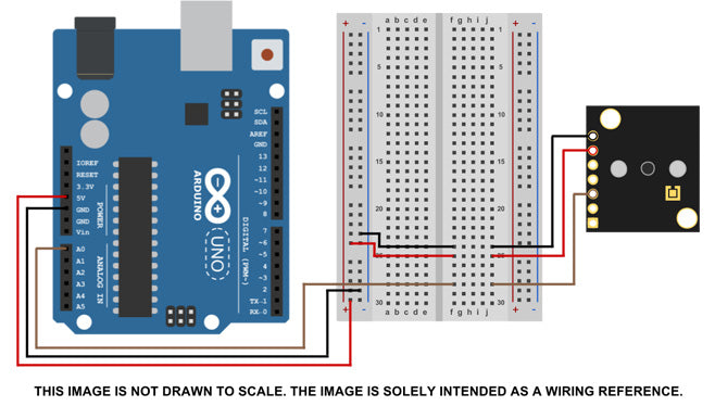
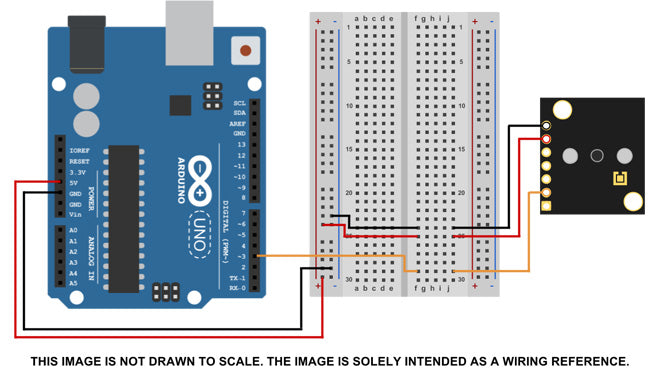
This article assumes you have the required equipment and necessary skill to operate a soldering iron. However, springloaded clip leads could certainly be used for solder free testing. 1. Install the Arduino Sketch software to your computer 2. Connect the sensor to the Arduino.New users may wish to follow one of the wiring diagrams included in this tutorial. You can connect the ultrasonic sensor directly to the Arduino with wires or use a breadboard. Attaching a 90-degree header to the ultrasonic sensor makes it very easy to attach it to a breadboard.
Breadboard - A thin plastic board used to hold electronic components (transistors, resistors, chips, etc.) that are wired together. Used to develop prototypes of electronic circuits, the boards can be reused for future jobs.3. Connect the Arduino to the computer. Please allow time for the computer to install the Arduino drivers.
Wiring Images
Arduino Coding: Part 1
Useful Information
Breadboard - A thin plastic board used to hold electronic components (transistors, resistors, chips, etc.) that are wired together. Used to develop prototypes of electronic circuits, the boards can be reused for future jobs. An image of how the internal nodes are connect is viewable here
ADC - Analog to Digital Converter. This takes a voltage and outputs it as bits. Typically as a 10-bit format (0 to 1024), some ADC's have other scales, so please reference the ADC datasheet.
Coding Definition:
analogRead - This is a command that tells the Arduino to read the Analog In pins. These pins are read using a 10-bit ADC. ADC - Analog to Digital Converter. This takes a voltage and outputs it in a bit format. Typically as a 10-bit format (0 to 1024), some ADC's have other scales, so please reference the ADC datasheet. delay() - This is a command that tells the Arduino to wait a length of time in milliseconds before performing the next task INPUT - Interface pin is acting as an input. The micro-controller will report or measure this pin if brought "HIGH" to voltages greater than 3.0VDC. This is used when coding the Arduino to read the PW or pulse width output of the ultrasonic sensor. pulseIn - This is a command that instructs the Arduino to read the PWM (Pulse Width Modulation) pins as an input. These pins are read as a length of time in uS. Serial.print() - This is a command that outputs the information to the computer or display connected to the Arduino. Text that is sent with this command and is contained inside of quotation marks and will be printed out in the display. Text that is sent without quotation marks is considered a variable. The value of the variable will be displayed not the text. Serial.println() - This is a command that tells the Arduino that this is the end of the current line and the next output will be the start of a new line following a carriage return. If this is not put in, all the data output by the Arduino will show up on one continuous line of text that can look very unorganized. variable - A container that holds information to be used later in the code to calculate, display, or manipulate a function or formula. The variable name is descriptive and should allow the reader of the code to understand the intended purpose of the variable especially within a function or formula. void - Section of code that performs a specific task. This is used to break up Arduino code into smaller more manageable sections.Arduino Comments
Comments are sections of code that are not read or sent to the device being coded. Instead comments are left as instruction or information to the coder or anyone who may review the code. Comments are designated by symbols that are inserted in code to tell the processor to ignore that line or section. In the Arduino coding platform, there are two different comment designators. The first comment designator for the Arduino is two slashes (//). This tells the processor to ignore everything that follows this symbol on the current line. As soon as a new line is started, the processor will start looking at the code again. This works well if a single line is being removed or a note is being written about a single line of code. The second comment designator for the Arduino is used to comment out large portions of code. Unlike the previous style that comments out one line, this style of comment has a start and stop designator. The start designator for this type of comment is a slash followed by an asterisk (/*). The end designator is the reverse of the start designator being an asterisk followed by a slash (*/). This comment style works well for removing sections of code that are not being used, sections being diagnosed and debugged, or at the start of the code for useful documentation such as purpose, date written, and the development platform.Code the Input & Variables
This section covers how to write a piece of code to read the sensor's output into the Arduino. If you would like the code pre-written to start from, jump to the Code Examples section. 1. Open the Arduino Sketch software. 2. Optional - Write several lines of code for basic record keeping. These lines typically include information on code use, the part number being used, platform, and the date started. This allows the code written to be a base code for other projects. An example is seen below. /* First Arduino Code Used to Read MaxSonar MB1013 Written for Arduino Uno Reading Pin# output (# being the pin for PW, AN, or TX) Started MM/DD/YY */ 3. Code the Arduino's input If the Analog Voltage is being read, this section will look like const int anPin = 0; If the Pulse Width is being read, this section will look like const int pwPin1 = 3; 4. Code any variables used within the code For Analog Voltage, this section will look like long anVolt, mm, inches; For Pulse Width, this section will look like long sensor, mm, inches; 5. Save the current file Typically it is a good idea to save the file as PartNumber_Output_Use for example MB1013_PW_Base.Arduino Coding Part 2
Code: Setup
This section covers writing the code section for the Arduino, how to communicate with the computer and set the the IO, input output, pin characteristics. Any section of code that runs some function, anything other than setting the input pins and variables, requires creation of a "void" section. When code is being written, care should be taken to ensure the correct case is being used. All characters are case sensitive. i.e. "Serial" always starts with a capital S. All code in this tutorial has the proper cases.Reading Analog Voltage
void setup (){ Serial.begin(9600); }Reading Pulse Width
void setup (){ Serial.begin(9600); } Notice the 9600 in the Serial.begin(9600) sets the BAUD rate used to read the Arduino for use in software such as HyperTerminal, Termite, MatLab, or any software that can read a COM Port.Code: Read the Sensor's Output
This section demonstrates how to write the code to read the sensor’s output pins with the Arduino.Reading Analog Voltage
The Arduino has a 10-bit ADC that it uses to read analog voltage signals. The MB1013 outputs a scale of 5mm per bit when reading Pin 3. This means every bit read by the Arduino has to be multiplied by 5 for the range in mm. To code this, use the example below. For the ultrasonic sensor scaling of a different ultrasonic sensor line please consult the sensor’s datasheet. void read_sensor (){ anVolt = analogRead(anPin); mm = anVolt*5; //Takes bit count and converts it to mm inches = mm/25.4; //Takes mm and converts it to inches }Reading Pulse Width
The MB1013 outputs a pulse width representation of distance on Pin 2. The scaling factor on this is 1mm per 1uS. This means if the Arduino reads 800uS, the target distance is 800mm away. For the sensor scaling of a different sensor line please consult the sensor’s datasheet. void read_sensor (){ sensor = pulseIn(pwPin1, HIGH); mm = sensor; //Takes the pulse width and tells Arduino it is equal to millimeters inches = mm/25.4; //Takes mm and converts it to inches }Arduino Coding Part 3
Code: Debug Section
The debugging section of Arduino code is great for reading the sensor's output on a computer, as well as diagnosing functions that are not operating properly. For example, if there is an LED that is supposed to change color when the ultrasonic sensor reports different range readings and is not changing, the debug section will report the range reading taken from the sensor. If the sensor's range is not changing, this section of code will show the range reading as steps are taken to see if the ultrasonic sensor position or the code is incorrect. void print_range (){ Serial.print("S1"); Serial.print("="); Serial.print(mm); Serial.print(" "); Serial.println(inches); }Code: Void Loop
The Arduino will continually repeat or loop through “void loop” section of code. By making smaller void sections, such as “read_sensor” or “print_range”, the code becomes much more manageable to code. For this section the code simply looks like this. void loop () { read_sensor(); print_range(); delay(100); } Because the ultrasonic sensor does not update every mS, the Delay slows down the Arduino so it only pulls a new range reading at set intervals. Typically this should be set to match the sensor read rate, in this case 100mS, a 10Hz rate.Review the Code
Now that several sections have been coded, it is best to verify that all the code is appropriately written and ready for uploading to the Arduino. If you wish to review the line information, the complete code for Pulse Width and Analog Voltage follow. The first way to do this is simply click the checkmark icon in the top left corner of the Arduino IDE. This will verify that all the code is properly written. Any errors will be displayed in the bottom of the IDE software in orange text Additionally, you can compare your code to the examples below.Analog Voltage
const int anPin = 0; long anVolt, mm, inches; void setup() { Serial.begin(9600); } void read_sensor(){ anVolt = analogRead(anPin); mm = anVolt * 5; inches = mm/25.4; } void print_range(){ Serial.print("S1"); Serial.print("="); Serial.print(mm); Serial.print(" "); Serial.println(inches); } void loop() { read_sensor(); print_range(); delay(100); }Pulse Width
const int pwPin1 = 3; long sensor, mm, inches; void setup() { Serial.begin(9600); pinMode(pwPin1, INPUT); } void read_sensor (){ sensor = pulseIn(pwPin1, HIGH); mm = sensor; inches = mm/25.4; } void print_range(){ Serial.print("S1"); Serial.print("="); Serial.print(mm); Serial.print(" "); Serial.println(inches); } void loop() { read_sensor(); print_range(); delay(100); }Code Downloads
LV-MaxSonar Code Downloads
Multiple Sensors Analog Voltage
XL-MaxSonar & XL-TrashSonar code Downloads
7.65 Meter Sensors
Multiple Sensors Analog Voltage
10 Meter Sensors
Multiple Sensors Analog Voltage
HR-MaxSonar & SC-MaxSonar Code Downloads
5 Meter Sensors
Multiple Sensors Analog Voltage
10 Meter Sensors


Articles related to the Article Above
Using a MaxSonar with an Arduino
MB7954 Shielded Cable
Power Supply Testing